GBS-8200 and GBS-8220 experiments part 1
GBS-82XX experiments part 2 now posted here (26th Jan 2015)
You may have seen on ebay and quite a few arcade accessory sites, a number of “GBS-8220 RGB / CGA / EGA / YUV to VGA Arcade Games HD Video Converter Boards”, which for the low cost promise a cheap solution to connecting a modern LCD monitor to retro consoles and video arcade systems. Based on user experiences posted on various message boards, the device does not always deliver. Various issues have been reported, from a complete lack of signal to poor video to speckles on the display and problems with moving video.
I was initially drawn into the investigation after answering a few questions on display issues on the EAB forum, http://eab.abime.net/showthread.php?t=75451 and subsequent conversations in another topic, http://eab.abime.net/showthread.php?t=66922, both threads are quite long. Since 2006 I have been involved with developing video systems for my day job and have gained some valuable experience in interfacing ‘non-standard’ video to modern displays. With this in mind I ordered a GBS-8200 board from Ebay and waited.
There are numerous forums posts that state to get the best out of this board you need a 5V high current, good quality, power supply and you should replace the electrolytic capacitors with higher quality ones. Being an Electronic Engineer with 16 years experience, I was dubious about this and set about investigating the board. A list of 21 items to test was created and depending on the results, I hoped to improve the basic video connections and obtain reliable, proper colour video images!
Whilst researching the devices on the board, I came across a thread the the SHMUPS (an abbreviation of Shoot-em-ups) board who has played with the software, http://shmups.system11.org/viewtopic.php?f=6&t=52172, this provided a link to the programming guide, which I did not have. I did have the TVIA-5725 datasheet. Playing with the software settings is for the next post on this topic, this one deals with the hardware.
There are two versions of the board available and two similar models. The GBS-8220 is a dual output board, the GBS-8200, which I have, has a single VGA output. The GBS-8220 is typically a V3 board, the GBS-8200 a V4 board. Easiest to show with some photos:
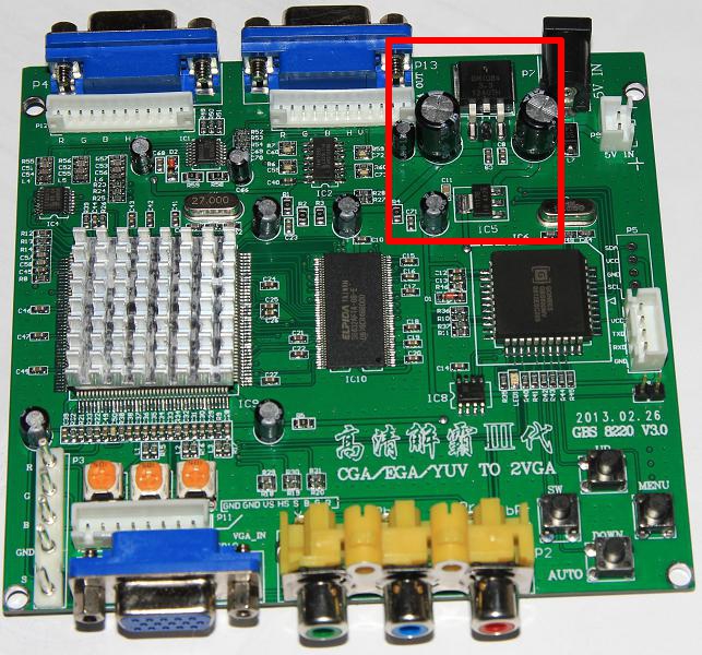

The highlighted areas show a crucial difference, the V4, GBS-8200 board, has a switchmode power converter, whereas the V3 board has a linear regulator on the the V4 GBS-8200 board only has 1 x VGA output! 😉 throughout this article, I will refer to the two boards collectively as the GBS-82XX.
My test setup

I use the cable supplied with the GBS-82XX board with the following connections:
Amiga signal Amiga pin Wire GBS marking
Red Video 3 Red R
Green Video 4 Green G
Blue Video 5 Blue B
Ground 16 Black GND
CSYNC 10 Yellow S (via 680 ohm resistor)
Do not use the YPbPr input, it will give you incorrect colours and you can not adjust the on-screen video settings as easily.
The following items were tested ‘in the lab’:
- Measure the +5V current using current probe and DMM
Measured 0.4A constant. - Measure the on-board 3.3V supply ripple, FFT DC to 200 MHz.
Around 50mV from the 3.3V switcher. Noise TBD
Around 20mV from the LDO.
TI app note slva115 LDO regulator stability. - Feed in 3.3V LVTTL sync signal, see what happens, does noise go away. No effect.
- Change 1.8V LDO regulator output capacitor from 22uF ceramic to Tantalum. This worked well, device no longer susceptible to susceptibility test.
- AC couple video, 220uF capacitors before termination/potentiometers.
Possible improvement, will test with a game - Test LM1881 see what happens.
Note outputs are not compatible with GBS82xx. 4.3V+ for logic 1 exceeds 3.6V max for Vih. Will be Ok with 680R resistor. - Tweak LM1881 Rset resistor, see what it does. Will not do anything on the Amiga video.
- Try CGA from the Amiga.
CGA works, there is a distinct left/right shift. Needs reduced sync amplitude, 680R from CSYNC of Amiga to GBS board. - Feed in composite PAL video signal to Y of YPbPR input, is the image stable?
Yes. Colourburst affects picture as expected, sparklies on screen. It has issues with black level clamping, most likely due to the colourburst reference. - Feed CVBS into Sync input. CVBS works, providing video is un-terminated.
- Check for 160 ohm resistor by pin 155, IREF generation.
- Check for filter circuit on PLL, 3K R + 33n and 3.3nF
There is a lot here, let me summarise some of the results:
- You do not need a high current power supply. The GBS-8200 board drew a maximum of 0.4A, this was measured with a DMM and a current monitor circuit, which provided current traces on an oscilloscope.
- The power supplies and noise levels were acceptable. Proper probing techniques together with a FFT plot were used to look at the onboard power supply noise on the 3.3V and 1.8V supplies. There was nothing unexpected, with FFT plots upto 200 MHz. There is absolutely no need to replace all the electrolytic capacitors on the board as they remove noise effectively.
- The 1.8V supply on the V4 board I have was unstable. A ceramic capacitor was used on the output of a linear regulator, one which was not stable (AMS1117) with this capacitor type. See http://www.ti.com/litv/pdf/slva115 for more details why. I replaced the capacitor with a 22uF tantalum bead. Prior to replacement, switching on/off my soldering iron transformer, caused the GBS-82XX board to glitch, now it does not. A simple but effective EMC susceptibility test, which this board failed. The original capacitor was a 10uF part with an ESR of 0.02 ohms, much too low for the regulator. Must check this on a V3 board.

Capacitor changed from ceramic to tantalum bead. Value is 22uF. - Do not connect the sync output of an Amiga or a LM1881 sync stripper direct to a GBS-82XX board. Both devices have a logic 1 level of >4.6V! The maximum input voltage for the TVIA-5725 device is 3.6V. If you exceed the absolute maximums, you start activating the ESD protection diodes on each input, never a good idea. The excess voltage is clamped to the device internal supply by these diodes, so the 3.3V internal (to the TVIA-5725 device in this instance) gets spikes every time the input is exceeded, pulling up it’s supply.This does affect the normal operation of the device and reduces reliability. Simply connecting the CSYNC output of an Amiga or the Composite sync output of an LM1881, to the GBS-82XX board, via a 680 ohm series resistor, removes this problem. I measured a signal amplitude of 3V.

Observations on the GBS-82XX boards
Whilst testing this board, I did make a few observations, which will focus future work:
- There are some scan-conversion artefacts, when connecting a 50Hz source to a 60 Hz monitor. This was most noticeable as a band of noise slowly moving up the display when viewed against a grey background. Changing the Amiga video to 60 Hz NTSC, removed the noise band.
- The de-interlacing method is not ideal, though this may be signal related. This was most noticeable on scene demos.
- Connecting the Amiga (and an Atari system) via the RGB inputs provided a good stable image but had some noise, this might be removable with ADC filtering.
- The TVIA-5725 can cope with a sync-disturbance and some non-standard video. A good sign.
- Using the GBS-82XX menu, reducing the sharpness from the default of 10, to 3 improved the display.
- I used the following video settings, Brightness=10, Contrast=90, Saturation = 50, Sharpness = 3.
Additional tests
I wanted to test something other than the Amiga, to see how well the GBS-82XX coped with another retro system. The Atari 7800 was nearby. My unit has been modified to output S-Video (Y/C). I then connected this to a RVA dev board, which converted the S-Video to YPbPr. The YPbPr video was fed into the GBS-8200 board. It sort of worked. I had trouble with the RVA board outputting black and white video from the Y/C source. I tried tweaking a few settings but this is a task for another time. Feeding in composite video, using a S-Video to composite lead from the Atari 7800 worked. Atari 7800 up-scaled to VGA:

For a 10 minute quick test, it showed the future potential of this board. There were some white speckles on the video though.
Though the RVA scan-doubler, when I get it working, may surpass it 😉
Future work
So I have played with the hardware, what’s left to do and what is next?
I want to check the SDRAM interface in more detail to ascertain if this contributes to the noise issues.
Play with the sampling and conversion settings of the TVIA-5725 device.
Experiment with the scan-converter.
Try 60 Hz games on the Amiga, see how they perform in terms of noise.
The I2C port now has a pin header soldered onto it and I observed that it operates at 87.3 KHz and has regular traffic. A Pickit serial, will be used to inject I2C commands for testing, this is no simple task, decoding what to try but will be fun!
Test a V3 board.
The next part will be in a couple of weeks, along with the next Hermes update

Have you noticed the distortion shown in this video? :
My relatively uninformed diagnosis is that there is some kind of frame buffer compression of the upscaled video, based on the fact that pixels that don’t move on the input video get moved on the output (even vertically, to different scan lines). What is the RAM chip on your board, and how big is it?
That’s caused by the de-interlacing engine. One of the software settings on the Raspberry Pi test interface, detailed here: http://shmups.system11.org/viewtopic.php?f=6&t=52172, removes this for the Amigas 288p screenmodes.
Work is ongoing to make the updated firmware easier to use.
A quick search on ebay shows there is now a version 5.0 for the GBS 8200. Any insight on this one?
Have you got a link to one of the ebay adverts?
I can only find the V4 PCBs on ebay UK.
Theres a “HD 9800 v. 5” here:
http://www.ebay.co.uk/itm/CGA-EGA-RGB-To-VGA-Video-Converter-Board-VGA-Output-Game-Convert-HD9800-GBS8200-/181632705793?pt=LH_DefaultDomain_3&hash=item2a4a272501
The intel-chip is the same size as the 8200’s.
The board i have, is the 8220 version; HD 9820, with a smaller intel chip, no version label, but a PCB-written date of 2014-07-11, like this one: http://www.ebay.co.uk/itm/NEW-Arcede-Game-Converter-Board-CGA-RGB-YUV-EGA-to-VGA-GBS-8220-Promotion-S2-/261957369293?hash=item3cfde03dcd
The image gets through, but its like a billion particles dancing.
The RVA is really interesting. It could be very useful for C64 S-video conversion.
The availability of good scalers for S-video is very limited. You can get something like the Framemeister XRGB-Mini, but it’s insanely expensive. I have ordered a few SCART adapters that’s said to be good, but I would like to see how they perform against the GBS8200 which I also have laying around.
I can assemble components, but my experience with designing and troubleshooting is limited and rusty. Do you plan to design a PCB, that we can make ourselves or at least a diagram showing how to assemble the components on a breadboard?
Thank you so much for your blog post. I had a Galaga arcade board set connected to an 8220 and the vertical sync was very erratic. I tried an 8200 and had the same issue. Turns out that the problem was in the fact that the Galaga drives a 5V composite sync into the Gonbes, which as you point out drives into an ASIC with a 3.3V power supply. Apparently the resulting current into the VCC protection diode on the comp sync input was enough to disrupt proper vertical sync operation. Interestingly enough, I had rock stable horizontal sync.
I inserted a 1K series resister (that was a value that was readily available) and – voila! – rock steady vertical sync also. Verified that now both the 8200 and 8220 boards work as expected.
CAUTION TO ALL: If your arcade drives 5V sync signals out, add a series resistor between the arcade sync(s) and the Gonbes converter. I used 1K ohms, but the 680 recommended by Ian should be fine. Limiting the clamp current to 10 mA should prevent any problems. Calculating the resistor value by: R = V/I = (5-3.3)/10mA = 1.7/10 Kohms = 170 ohms. I’d go higher to be safe. 680 = 4 x 170, limiting clamp current to 2.5mA, a more conservative (and safer) value. Using a larger resistor should be even better, as the only downside is that the sync edges will be slower. Assuming a cable + Gonbes load capacitance of 100pf and a 1K resistor, tRC=100pf x 1K = 100E-12 x 1E3 = 100 ns = 0.1 uS. 0.1uS is small relative to a 3-4 uS sync time, hence even 1K is a reasonable value which will limit diode clamp current to a meager 1.7 mA…even less stress on the Gonbes clamp diode(s).
Strangely enough, when I add a small resistance to my CSYNC signal from the Amiga, my input gets blanked. Once i trim down the resistance to around ~300Ohms, i get a signal again. I have the GBS8220 (HD9820).
I am trying to get a GBS 8200 v4.0 board to work with a printing press console made in 1987 that displays the settings for the print cylinders, ink, and water settings. the original monitor was a Sharp CZ-603d multisync (15khz, 31khz) which was only used on this console and a Japanese gamming system only sold in Japan. (NEC X68000),
(when I say console, its not a game console but a big table that is used to control the printing press).
The console uses what looks to be a CGA board with R, G, B, HS, VS, and GND wires. I have wired it to the 8200 using P11 and also tried joining the sync’s and using P3. I am using a 5v – 2A supply and have wired it in the dc jack and also tried P9.
I can get the signal from my console but cannot fully lock onto it. it just keeps rolling. I can see the words “ink” “water”and “unit”. The screen is full of red blocks which should be smooth red background. The program showing the settings is not that graphically demanding and should be a simple display. Has anyone using a GBS 8200 seen anything of this nature when trying to view a 15khz signal?
a video of what I am seeing with the print console can be seen at this link
For install tantalum capacitor 22uf (C11 location), where the polarity – ?
Does the GBS-82XX sync on other frequencis than 15, 24 and 31KHz? Is it possible to view MDA, 18KHz..?https://en.wikipedia.org/wiki/IBM_Monochrome_Display_Adapter
Hi,
Should do. I’ve used a GBS8200 with a LM1881 sync separator to upscale 19.2kHz composite monochrome video from HP test equipment.
Hi, could you please provide more details regarding the configuration?
I have a HP8924c with 19.2kHz outpout
Best Regards
Yiannis
Hello.
please tell me how you solved the problem, connect to the MDA frequency -18.43 kHz to GLS8200.
vitoptima@gmail.com
Sorry, have never worked with MDA video so can not provide any advice on how to connect it.
I’ve found that using 5v 2a is not enough and use 12v, the gonbes paired with a SLG that has been set to my device… Some need even lines others odd and the width of the scan lines is crucial as well. I’m self taught but certified in computer based electronics so forgive my lack of technical speak. I figured the SLG I chose uses in line power so that in itself helps feed from the maximum voltage requirement, no overheating issues nor any others, it runs flawlessly on my MVS-4. Also using an LED made by a reputable company helps, I chose a model that automatically detects signal and auto on kicks in likewise to the auto off. See my video, https://www.youtube.com/watch?v=fpoKVfHLzZk
Hi, I am trying to connect a CNC machine to normal VGA monitor through GBS8200, but no success. Machine has R,G,B,H and V outputs. H frequency is around 24kHz, V is 50Hz. I do not get any picture at all. Only NO SIGNAL. May I connect H and V together (how?) and connect to RGBS input?
I try to do the same thing, my signal has a horizontal frequency of 18.45Khz, and vertical 50Hz with no luck. I only get something unsynchronized, when i select a Picture on the GBS8200 of 1024×768.
I have a Haas CNC machine with a monochrome CRT that terminates in a db9m. I just purchased a GBS-8200 with the understanding that it would accept my input signal. The documentation is a little sketchy for my tastes, only indicates “auto-scan” for the input pins. I would love to know if anyone has any experience with this. It sounds so simple… I’m tempted to connect it basically at random and see what happens
Hi, i have some problems, how can i fix the vertical lines?
Im using Mega Drive 1 jap, scart cable and 680 resistor on sync.
Please see the video.
Thank you!
I had some issues with my A500 and GBS8200 where the image was not stable. It was shifting back and forth around the screen by a pixel or so, rather annoying. Otherwise though no problems. Based on an idea I got from an IBM CGA/EGA to analog converter I have fixed this problem. Instead of using the Composite sync from the Amiga, I used the H and V sync and a 74F86 and Xor’d the 2 signals together then outputted to the csync on the GBS8200. I did fit a 1uf capacitor to the IC but this possibly wasn’t necessary. The result a rock solid display. Hope this helps someone.
s: Is it possible to make a picture how to connect this ?
I can’t do up an image to show this right now, but basically, connect H sync to pin 1 on the 74F86, then V sync to pin 2. Connect pin 3 of the 74f86 to csync on the GBS82XX. I think he’s also saying he put 1uF capacitor between the Amiga signals and the 74F86. That part is a bit unclear, but putting the resistor on the Amiga lines should produce the same output as if you put the resistor on the output of pin 3, if that’s what he meant and not going into the 74F86.
Hi,
I’ve covered part of the circuit here:
https://ianstedman.wordpress.com/2016/07/06/synchronise-your-video-engines/
Look for ‘OR/XOR sync combiner circuit’.
Be careful with some of the TTL logic, some newer 5V CMOS variants will cause issues, as discussed in that post. The older 74F logic, I seem to remember is around 2-3V for logic 1 so should be Ok.
There is no need to add a 1uF capacitor on TTL signals, providing you connect the ground signals.
Excellent page you have constructed here. Lots of useful information.


I have a question. Do you know what causes these jailbars I am seeing on my GBS8200? They are present constantly, no matter what system I connect to it.
What are the exact specs for the capacitor you swapped? I use these in a bowling center to convert RGBS to VGA, and every time a pin setter runs, even lane 6, the LED TV on lane 1 flickers. Lanes are placed in pairs on separate breakers, and are 230V 3-phase, and TVs are too on a different breaker from the pin setters. I have to chalk this up to your capacitor C11 mentioned, and plan on swapping them. I did find SMD tantalum capacitors, so I wondered what voltage and resistance ratings it has?
Any normal tantalum capacitor, 10V of greater, 22uF. Do not pick a low ESR tantalum, the correct range of values is 0.3 to 22 ohm.
Hope it works.
What about polarity? Where is the positive side on the PCB?
Take a look here:
https://ianstedman.files.wordpress.com/2015/01/capacitor_to_change-medium.jpg?w=509&h=387
I identified the + and – pins. You can always check polarity with a DMM.
Hi everyone,
I have a friend with a old free standing arcade came called Bomb Jack a 1984 vintage.
First he asked me if I could fit a new power supply as it had failed.
So I found on Ebay a 5V 16a and 12V power supply and fitted this into his machine, the sound worked but the old CRT monitor did not, after messing about with it and checking connections etc decided to change the old CRT for a 19″ lcd Dell and fit a GBS8200 convertor, however, first switch on was unsuccessful as I found on my second visit I had in fact plugged the VGA cable into the VGA input! Doh!
I brought the GBS8200 from an arcade games supplier and paid top money as any technical problems I may have hoped they would be helpful, also it was described and sold as a 2x VGA output this was how I managed to plug into the wrong port on my first visit. (but no excuses for making fundamental mistake).
I stumbled across this discussion as I`m looking to stop the LCD screen jumping, now that I have a picture. Iv`e been through the on screen menu a dozen times changing clamp settings etc, pressing the menu and the SW buttons many times but the image jumps around making it unusable.
I have checked the 5 wires, R G B, Ground and CSYNC for continuity from the main board they terminate at the top right hand corner of the main board and are soldered, they check out to 0 ohms all connecting good, I was looking for a fault with the main board but this may Not be the case reading these discussions?
I read with interest replacing the capacitor and to fit a 680 ohm resistor in the CSYNC wire before connecting it to the GBS8200 do you think this could stop the image jumping around the screen?
I could make the capacitor and the resistor connections myself as Iv`e been a service engineer for many years but working on surface mount components if becoming increasingly difficult!
The other big problem is that the GBS8200 does Not hold a memory.
When I switch the machine off and then back on the settings have all returned to the original state.
I even have to change the Chinese back to English every time, am I missing something in the program? Also the menu is on it`s side as the screen is mounted portrait, can I rotate it? The game picture is correct orientation apart from the erratic screen jump making it unusable.
Please, any help or advise, “Bomb Jack” Kellymont
Hi,
Catching up with comments.
Try the 680 ohm resistor on CSYNC. It’s cheap and easy to apply. The capacitor change is mainly to cut down on susceptibility to external noise causing a brief interruption to the display. It’s recommended but not mandatory.
Is the Bombjack game a Jamma format game?
I’ve not specifically checked how to use a JAMMA board as I’ve never owned one. Would need to check if it has CSYNC or separate H/V sync signals.
Not sure why your board does not hold it’s settings, maybe it is faulty as mine and other users board hold the settings.
Ian
Hi, thanks for the reply.
I will try the 680 ohm resistor first on the CSYNC, as you say cheap and easy to apply but, if fitting the capacitor gives a better result and is kinder on other components on the board giving longevity I will attempt the insertion of that also.
Yes I believe the Bombjack game is a original Jamma Format Game (I Think) as I`m not too familiar yet with gaming machines, it`s actually two boards about (A4 paper size) mounted back to back with obviously a gap between and the components facing outside.
I can only find the one CSYNC wire from the Jamma board it`s yellow and in the same group as the R G B and Black ground wires.
I was surprised at the voltage drop from the power supply, with the GBS8200 connected, I have exactly 5v at the two pin connection point by adjusting the power supply but it puts the 12v line above 13v not much I can do about that as there is only one adjustment from the power supply.
Do you think I could have damaged the 8200 by connecting the VGA cable from the screen into the input port on my first visit? I don’t think it has, and I don’t know why it is not holding memory?
If I can’t get it to hold memory ill contact the supplier and they can supply the board I ordered, however I don’t need to run two screens as on the 8220 so the 8200 will be fine with a component change if it holds the image steady and holds a memory??
Thanks again
Steve
HI, Bomb Jack Kellymont again!
I have contacted the supplier of the 8200 and they said it must be faulty if it does not hold a memory, said they will replace it when they receive the faulty one. Great!, a 30 mile round trip to my friend`s and then to remove it post it back and wait for a replacement. I may get the 8220 this time as it was the one I ordered, however, as long as it holds memory that will be a start, I will do the 680 ohm on the CSYNC and then see how it goes!
If I am still having problems when I fit the new board with unsatisfactory picture and more modifications are recommended on this 82xx is there someone who can carry out this work for me?
Bomb Jack Kellymont!
Hi Again Bomb Jack Kellymont
I fitted the 680 ohm resistor to the CSYNC line, it`s made the world of difference. Thanks!
The only problem now is that the picture has horizontal lines, please see these Links.
The 8200 does not hold memory so I am returning this one and perhaps get a 8220?
Any ideas what could be causing these lines, the only modification is the resistor in the CSYNC line and I have tried all clamp settings etc
Cheers