GBS-8200 and GBS-8220 experiments part 1
GBS-82XX experiments part 2 now posted here (26th Jan 2015)
You may have seen on ebay and quite a few arcade accessory sites, a number of “GBS-8220 RGB / CGA / EGA / YUV to VGA Arcade Games HD Video Converter Boards”, which for the low cost promise a cheap solution to connecting a modern LCD monitor to retro consoles and video arcade systems. Based on user experiences posted on various message boards, the device does not always deliver. Various issues have been reported, from a complete lack of signal to poor video to speckles on the display and problems with moving video.
I was initially drawn into the investigation after answering a few questions on display issues on the EAB forum, http://eab.abime.net/showthread.php?t=75451 and subsequent conversations in another topic, http://eab.abime.net/showthread.php?t=66922, both threads are quite long. Since 2006 I have been involved with developing video systems for my day job and have gained some valuable experience in interfacing ‘non-standard’ video to modern displays. With this in mind I ordered a GBS-8200 board from Ebay and waited.
There are numerous forums posts that state to get the best out of this board you need a 5V high current, good quality, power supply and you should replace the electrolytic capacitors with higher quality ones. Being an Electronic Engineer with 16 years experience, I was dubious about this and set about investigating the board. A list of 21 items to test was created and depending on the results, I hoped to improve the basic video connections and obtain reliable, proper colour video images!
Whilst researching the devices on the board, I came across a thread the the SHMUPS (an abbreviation of Shoot-em-ups) board who has played with the software, http://shmups.system11.org/viewtopic.php?f=6&t=52172, this provided a link to the programming guide, which I did not have. I did have the TVIA-5725 datasheet. Playing with the software settings is for the next post on this topic, this one deals with the hardware.
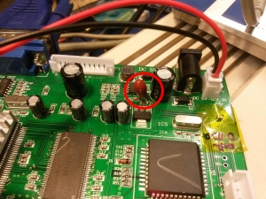
There are two versions of the board available and two similar models. The GBS-8220 is a dual output board, the GBS-8200, which I have, has a single VGA output. The GBS-8220 is typically a V3 board, the GBS-8200 a V4 board. Easiest to show with some photos:


The highlighted areas show a crucial difference, the V4, GBS-8200 board, has a switchmode power converter, whereas the V3 board has a linear regulator on the the V4 GBS-8200 board only has 1 x VGA output! 😉 throughout this article, I will refer to the two boards collectively as the GBS-82XX.
My test setup

I use the cable supplied with the GBS-82XX board with the following connections:
Amiga signal Amiga pin Wire GBS marking
Red Video 3 Red R
Green Video 4 Green G
Blue Video 5 Blue B
Ground 16 Black GND
CSYNC 10 Yellow S (via 680 ohm resistor)
Do not use the YPbPr input, it will give you incorrect colours and you can not adjust the on-screen video settings as easily.
The following items were tested ‘in the lab’:
- Measure the +5V current using current probe and DMM
Measured 0.4A constant. - Measure the on-board 3.3V supply ripple, FFT DC to 200 MHz.
Around 50mV from the 3.3V switcher. Noise TBD
Around 20mV from the LDO.
TI app note slva115 LDO regulator stability. - Feed in 3.3V LVTTL sync signal, see what happens, does noise go away. No effect.
- Change 1.8V LDO regulator output capacitor from 22uF ceramic to Tantalum. This worked well, device no longer susceptible to susceptibility test.
- AC couple video, 220uF capacitors before termination/potentiometers.
Possible improvement, will test with a game - Test LM1881 see what happens.
Note outputs are not compatible with GBS82xx. 4.3V+ for logic 1 exceeds 3.6V max for Vih. Will be Ok with 680R resistor. - Tweak LM1881 Rset resistor, see what it does. Will not do anything on the Amiga video.
- Try CGA from the Amiga.
CGA works, there is a distinct left/right shift. Needs reduced sync amplitude, 680R from CSYNC of Amiga to GBS board. - Feed in composite PAL video signal to Y of YPbPR input, is the image stable?
Yes. Colourburst affects picture as expected, sparklies on screen. It has issues with black level clamping, most likely due to the colourburst reference. - Feed CVBS into Sync input. CVBS works, providing video is un-terminated.
- Check for 160 ohm resistor by pin 155, IREF generation.
- Check for filter circuit on PLL, 3K R + 33n and 3.3nF
There is a lot here, let me summarise some of the results:
- You do not need a high current power supply. The GBS-8200 board drew a maximum of 0.4A, this was measured with a DMM and a current monitor circuit, which provided current traces on an oscilloscope.
- The power supplies and noise levels were acceptable. Proper probing techniques together with a FFT plot were used to look at the onboard power supply noise on the 3.3V and 1.8V supplies. There was nothing unexpected, with FFT plots upto 200 MHz. There is absolutely no need to replace all the electrolytic capacitors on the board as they remove noise effectively.
- The 1.8V supply on the V4 board I have was unstable. A ceramic capacitor was used on the output of a linear regulator, one which was not stable (AMS1117) with this capacitor type. See http://www.ti.com/litv/pdf/slva115 for more details why. I replaced the capacitor with a 22uF tantalum bead. Prior to replacement, switching on/off my soldering iron transformer, caused the GBS-82XX board to glitch, now it does not. A simple but effective EMC susceptibility test, which this board failed. The original capacitor was a 10uF part with an ESR of 0.02 ohms, much too low for the regulator. Must check this on a V3 board.
Capacitor changed from ceramic to tantalum bead. Value is 22uF. - Do not connect the sync output of an Amiga or a LM1881 sync stripper direct to a GBS-82XX board. Both devices have a logic 1 level of >4.6V! The maximum input voltage for the TVIA-5725 device is 3.6V. If you exceed the absolute maximums, you start activating the ESD protection diodes on each input, never a good idea. The excess voltage is clamped to the device internal supply by these diodes, so the 3.3V internal (to the TVIA-5725 device in this instance) gets spikes every time the input is exceeded, pulling up it’s supply.This does affect the normal operation of the device and reduces reliability. Simply connecting the CSYNC output of an Amiga or the Composite sync output of an LM1881, to the GBS-82XX board, via a 680 ohm series resistor, removes this problem. I measured a signal amplitude of 3V.

Observations on the GBS-82XX boards
Whilst testing this board, I did make a few observations, which will focus future work:
- There are some scan-conversion artefacts, when connecting a 50Hz source to a 60 Hz monitor. This was most noticeable as a band of noise slowly moving up the display when viewed against a grey background. Changing the Amiga video to 60 Hz NTSC, removed the noise band.
- The de-interlacing method is not ideal, though this may be signal related. This was most noticeable on scene demos.
- Connecting the Amiga (and an Atari system) via the RGB inputs provided a good stable image but had some noise, this might be removable with ADC filtering.
- The TVIA-5725 can cope with a sync-disturbance and some non-standard video. A good sign.
- Using the GBS-82XX menu, reducing the sharpness from the default of 10, to 3 improved the display.
- I used the following video settings, Brightness=10, Contrast=90, Saturation = 50, Sharpness = 3.
Additional tests
I wanted to test something other than the Amiga, to see how well the GBS-82XX coped with another retro system. The Atari 7800 was nearby. My unit has been modified to output S-Video (Y/C). I then connected this to a RVA dev board, which converted the S-Video to YPbPr. The YPbPr video was fed into the GBS-8200 board. It sort of worked. I had trouble with the RVA board outputting black and white video from the Y/C source. I tried tweaking a few settings but this is a task for another time. Feeding in composite video, using a S-Video to composite lead from the Atari 7800 worked. Atari 7800 up-scaled to VGA:

For a 10 minute quick test, it showed the future potential of this board. There were some white speckles on the video though.
Though the RVA scan-doubler, when I get it working, may surpass it 😉
Future work
So I have played with the hardware, what’s left to do and what is next?
I want to check the SDRAM interface in more detail to ascertain if this contributes to the noise issues.
Play with the sampling and conversion settings of the TVIA-5725 device.
Experiment with the scan-converter.
Try 60 Hz games on the Amiga, see how they perform in terms of noise.
The I2C port now has a pin header soldered onto it and I observed that it operates at 87.3 KHz and has regular traffic. A Pickit serial, will be used to inject I2C commands for testing, this is no simple task, decoding what to try but will be fun!
Test a V3 board.
The next part will be in a couple of weeks, along with the next Hermes update

You know why I can’t change geometry settings when using RGBHV? Inputting 800×600@60hz vga signal. I wanna use the Gbs-8200 just for a resizer/scaler.
HI,
A500
I have both boards v3 and v4 the v3 board worked straight out of the box
I did use your video settings . The v3 board has as vertical sparkles running regardless
I amend my previous post. The 8200 v4 has vertical bands/ strips of noise and sparkles moving bottom to top. The 8220 v3 worked straight out of the box it two x VGA out.
I did use your video settings .
Hi, is C5 on the V3 revision the equivalent of the one on the V4 that you replaced. Does the V3 one need replacing?
I’m guessing the V3 board is better as no noisy switched mode supply no?
People like to connect their AtariST in high resolution directly to VGA. Works fine. But the low rez does not work and needs conversion (or a slow scan monitor). Does the 82xx accept a 72Hz/31.5kHz signal? Would be cool, just plug one of the available RGB+Mono ST to VGA adaptors into the 82xx and you don’t need to dig through monitors to find one displaying STlow and SThigh.
Does anyone have any experience of eliminating RGB signal crosstalk/ ghosting?
I am using the GBS 8220 converters in a project which requires 4 of these boards in 2 pairs. I started with one board and after my initial nightmare of having to create a sync combiner to convert 15kHz RGBHV to RGB Combined sync for a stable image I’ve run into a head scratcher at almost the last hurdle. The prototype sync circuit works well but here’s where it all goes wonky…..
The twin RGBHV outputs I am converting are coming from a 25 metre cable directly from the video output source and into a splitter board. This splitter separates the two RGB sources in the cable, and provides Ground and HV sync lines for each connector. I have wired 2 DB25 connectors which feed into the sync combiner circuit and into the GBS 8220. This trimmer pots in the sync combiner I have obtained a stable and clear image, hurrah….
That is until I added the second GBS8220 into the equation, when the second set of RGB signals (which travel down the same cable) is plugged into the second board, I see a faint ghosted image of each output on each LCD screen. When the RGBHV signal cable is plugged into the original 15kHz Monitors this does not happen. Nor does it occur when one monitor is fed with the original signal and the other signal is fed into the first converter card. I’m having trouble finding reason and the solution as to why the ghosting is appearing on each display coming out of the converter boards.
I’ve investigated the grounding, coupling the RGB signals, separate sync circuits for each converter card but all to no avail.
If anyone has any information or a direction to point me in I would be very very grateful
Hi,
Are you buffering the video where it splits?
Something like this circuit, http://www.elcircuit.com/2012/03/video-distribution-amplifier.html will help.
The resistors R11 and R12 in that circuit are important to match the impedance of the driver to the transmission line, get this wrong and you will have reflections, which cause ghosted images.
https://www.youtube.com/watch?v=p2Hd0KO28FU try this
Hi, I’m trying to get the V3 of the board working with the Spectrum 128K Grey version using the RGB port, I’m getting no signal on the screen. I know the RGB port is good on the Spec. So do I have a faulty unit or doing something wrong.
Thanks
You have the Amiga CSync going to the GBS yellow wire above. I believe it should be going to gray, as per the second part of your article. In fact I tried it both ways: yellow did not work but gray did.
Hi.
I described my fight with GBS-8220 in this post: https://oldcrap.org/2018/03/11/cga-to-vga-scaling-with-gbs-8220-board/
Finally managed to connect CGA to VGA via RGBS, but never seen RGBHV working.
Cheers
Pawel
Hi Pawel,
have you ever seen any succesfull conversion using 50Hz/15,6kHz noninterlaced signal? My GBS accept only interlaced video B/W signal, any type of noninterlaced signals result in “No signal”. When using some 60Hz signal, noninterlaced signal is accepted everytime.
Ivan
Hi Ivan. I was only successful with 60Hz signal. I never managed to run Amiga video through GBS which your theory can explain as I suppose it runs at 50Hz in PAL mode by default. I can try interlaced modes and see if it confirms next week.
Hi!
i got myself a HD Video Converter Board HD9800/GBS8200 for my taito landing gear arcade game,but when connected it only shows parts of the graphics and nothing in 3D,only black spaces.do you have any idea why its doing this?
Hi. Thank you for your explanation. Brilliant! I’m trying to understand your steps, especially in the power supply, to upgrade a board on my own. You replace the ceramic capacitor with a tantalum one. Could you give me a hint about the polarity? Plus left or right? I don’t have a clue how you figgured this out. I can’t see any copper lines (middle layer?)
Hi. My NEW BGS-8220 Rev 3.0 (2015.06.01) board (from ebay) is missing a capacitor at C28. I can’t get any signal no matter what the input is. The input image rarely shows up for a split second at power up and after input switch but then it goes away and I get a black screen with “NO SIGNAL”. I don’t know if C28 is supposed to be there or not but I’d like to try to put a component there before buying another unit. Would anyone be able to tell me what the value of C28 is? (or confirm that C28 isn’t needed for normal operation)
I have C28 and it gives me 0.1nF but I measured soldered. Anyway it gives the same value as other capacitors in that row so you may try by comparing or remove one.
But I had same problems with my board, impossible to sync to anything. Then I played a bit with the sync signals and were able to get it working. You may see my post here, maybe it helps: https://oldcrap.org/2018/03/11/cga-to-vga-scaling-with-gbs-8220-board/
Thanks Pawel for the reply and the URL. I had actually read your blog about your CGA journey. That was what gave me the idea to try to connect a VGA input and try to use the GBS8220 as a pass-through. I got a terribly shuffled input image (the image was visible but it was cut up into little tiles and those tiles were shuffled around) and there was no screen refresh.. Just a static image. Which made me look for issues with the board in the first place and got me to notice the absence of C28. In the meantime I actually got RGBS(ync) working – I had forgotten to bring the Sync level down into range with the 680R ohm resistor (Amiga A2000 video signal). Once I added that, the AUTO button found the correct timing. So RGBS works without C28.
I had actually tried what you suggested, however I measured ~50..~90 nF’s on those capacitors which is odd in comparison to yours’. My Fluke multimeter can’t seem measure anything below 1nF, so finding (and confirming) a 0.1nF will be tricky. On a side note, I did try and put a 100nF at C28 which made no difference at all. Anyways, thanks for your reply once again.
the GBS8220 can be used to connect a PC equipped with a modern video card to a 15Khz CRT monitor? thanks in advance for your reply
Could you confirm the polarity of the centre tip required for the power supply please?
Should it be negative or positive centre? I am thinking of getting an GBS-8220 Rev 4.0.
Hey.
How can i make my gbs8200 work with pal 50hz
Ntsc works ok. Both colors and stability is fine.
Attempted with a lm1881n tryied with different voltage and setups. The ref setup in the datasheet with low voltage 3.3 or 3.7 gave me a unstable picture but colors seems ok. With 5v only no signal.
What to doo?
I live en denmark i would like pal signal…
Source i a amiga 500 with db23 rgb