GBS-8200 and GBS-8220 experiments part 2
Work has continued, experimenting with these low cost but potentially highly capable video adaptor boards.
Fixing the random speckles on the display
I believe I have found the cause of the occasional white speckles seen on the display. The default setting for the GBS-82XX board is to clock the 166 MHZ speed grade SDRAM at 162 MHz. It appears to be worse if the Hynix HY57V643220DT-6 is fitted compared to the EtronTech EM638325TS-6G device, which appears to be fine.
I measured the SDRAM clock at 162 MHz and recorded this:

Whilst the signal is a bit noisy, it does not violate the +/-2V overshoot/undershoot limits of the SDRAM devices used.
The simplest fix was to reduce the SDRAM clock speed to 129.6 MHz, with a single I2C write. This has fixed the issue. Halving the SDRAM speed to 81 MHz caused distortion on the video, the next speed increment of 108 MHz was sufficient for 1360×768 pixel output. A proper fix would be to adjust the timing of the DQM strobes with regard to the data bus as on SDRAM the DQM strobes clock the data out of the SDRAM. If this is adjusted, you also need to consider the timing of the SDRAM clock to the control bus (RAS, CAS, CKE, CS, BS0/1 and WE) and the Data bus. This is not too difficult if you have the PCB artworks as you can measure the PCB track lengths and adjust the timing by 7ps/mm. With the GBS-82XX board, it would be tricky and fraught with false starts. We could of course measure it and adjust accordingly, or reduce the clock speed by 20% and have more timing margin (an extra nanosecond) on the clock.
Now that the speckling problem appears to be fixed, I am looking at some general video quality issues. When using a 50 Hz PAL screen-mode, scan-converted to 60 Hz, there are some noise bands, particularly noticeable on a grey Workbench background. It is hoped that some digital filtering/sampling will help alleviate this.
Synchronising the GBS-82XX
I have experimented with different ways to synchronise the GBS-82XX device. As those of you that have experimented with the board now, sometimes it can be a bit ‘hit and miss’ with the video source (games console or computer).
When using the GBS-82XX with the Amiga, this is the cable I use:

The 680 ohm resistor is essential. It reduces the CMOS Composite sync signal from the Amiga to < 3.6V. The TVIA-5725, the device under the big heatsink, accepts a maximum voltage of +3.6V and a minimum voltage of -0.3V. The Amiga’s video sync, measured on the A1200, looks like this: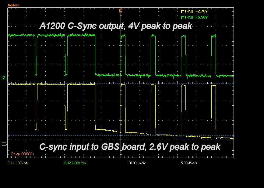
The TVIA-5725 accepts a 3.3V TTL signal, via a Schmitt input, this changes logic levels slightly so a logic 1 is 2.4V to 3.3V, and a logic 0 is 0 to 1.0V. The 680 Ohm resistor works as the GBS-82XX follows the Vesa VSIS specification, which requires synchronisation inputs to have a 2K impedance to ground. My 680 ohm resistor (+47 ohms in the Amiga), creates a potential divider, reducing the signal level to a safer level. This is cheap and easy to implement and does not degrade the video sync significantly.
A number of people use the venerable LM1881 video sync separator, any device or circuit that uses this, should have the 680 ohm resistor added as shown above. The LM1881 outputs 4-5V sync levels that are not compatible with the GBS-82XX/TVIA-5725. Alternative devices are the EL1883 or the LMH1980 but they are not available in hobbyist friendly DIP packaging.
I have tested the LMH1980 with the Amiga, I used the composite video output of the A1200 to create LVTTL (3.3V) HSYNC, VSYNC and CSYNC. The GBS-8200 I have synchronised with the CSYNC perfectly, the same as using a resistor. It did not work reliably when I supplied separate HSYNC and VSYNC, I had a very wavy display.
A final note, the GBS-8200 did synchronise to the Composite video output of the A1200 but it is not recommended. The 2V (approx) video contains colour information that is not filtered out and would in all eventualities, cause problems at a later date.
Cleaning up the power supplies
I have been reading numerous web-forums on GBS-8200/GBS-8220 problems to look for common trends and solutions. One topic that crops up a lot is related to the power supplies. I have already proven, in part one, that a 5V 2A supply is not required.
During my testing, I noticed an occasional, high frequency, burst of noise, on the +3.3V supply. I traced it back through the circuit to the power input. Changing the timebase of the oscilloscope, I spotted something important, it happened at 20ms/50Hz intervals. In the UK and Europe, the AC mains operates at 50Hz so when you see a 50Hz noise pulse, you know where it came from. Currently my GBS-8200 is powered from my bench power supply, built 20 years ago, with 3 linear regulators and still on the original electrolytic capacitors.
Also connected to the +5V output was my 5V to 3.3V TTL buffer board. Two of the eight inputs were in use, the other six were floating. I made a mistake here. You should never leave TTL inputs unconnected, they will pick up noise and oscillate, in this instance, they picked up 50Hz mains noise. Quickly dis-connecting the buffer board, removed the noise. The 3.3V (switchmode) and 1.8V (linear) regulator supplies now have about 20-30mV of noise, perfectly acceptable.
To ensure I do not have any further conducted noise issues I added a clip on ferrite bead:
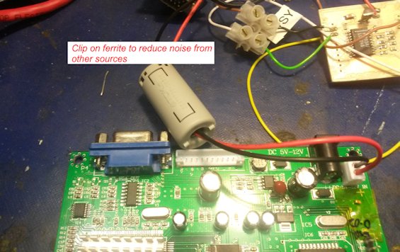
You can see the buffer board in the top right of the photo. Whilst this ferrite was a little large, it did cut the noise out. If you are using the DC power jack (the black plug) either pick a PSU that has a ferrite fitted or measure the cable diameter and purchase a clip-on ferrite from a local supplier or ebay. I spent two hours trying to work out where the noise was coming from, reading datasheets and measuring the board.
To date I have changed a single capacitor on the board. I briefly touched on this in my first post but after additional testing, I am happy to confirm it needs changing.
Here it is:

The 1.8V regulator is used for the core supply of the TVIA-5725. with a ceramic capacitor, I was able to cause the power supply to glitch by switching my overhead inepection light on/off or my soldering iron transformer. Since changing it to a 16V, 22uF, tantalum bead capacitor, this has not happened. The original capacitor, shown under Kapton tape, had an ESR of 0.02 ohm, the recommended range for the LM1117 (similar to the AMS1117 used here) is 0.3 to 22 ohms! The part I fitted had an ESR of around 2 ohms.
The software settings solution?
Some people ask what the final software settings solution will be?
My preferred option is to use an Arduino Nano like this:

(Image from http://arduino.cc/en/Main/arduinoBoardNano)
This would be used to read and write the I2C commands to the TVIA-5725 device which provides the video scaling functions, among others. It is readily available and clones can be cheaply procured, finally it can be easily updated using the Arduino environment.
My aim is to make the design data readily available, for free. This will include the video settings. I’ve seen too many scammers on ebay selling ‘Amiga modified’ equipment for extortionate prices, I will not have this solution exploited.
Another option, still using the Arduino approach is a module that piggybacks on the 8051 microcontroller clone on the GBS board. This would allow access to the onboard switches and no wiring. The downside is it would be more expensive.
Until the final settings are known, the end solution is fluid.
Until the next update.

Anyone have a problem with the GBS-8200 or GBS8220 running the screen pink after a few minutes? I have a number of these cards that are all doing this in EGA mode. Haven’t a CGA signal to try at the moment so don’t know if this is specific to EGA.
The game I am trying to run on LCD is Atari RUSH THE ROCK.
I’ve tried the 680R resistor on the Sync line.
Suggestions welcome – I have five boards all doing the same thing both with the game and my Sencore Video Signal Generator (EGA setting 25Khz and 60Hz).
Thanks!
Further testing with my Sencore signal generator – the same boards running CGA input with the same LCD monitor do NOT turn pink, colours are stable. This is definitely related to the EGA mode as far as I can tell. EGA sync (composite) is 25KHz and 60Hz. The card does not work if the sync is separate – “No Signal”.
Update – the problem was traced to the CLAMP settings after all.
25KHz EGA mode – set Clamp st=56, Clamp sp=61
That fixed my board issue of it turning pink after a little while in an Atari RUSH THE ROCK.
Just a final note, I checked a few other of our 8200s that had notes on them (turn pink) and all are working properly now as long as the Clamp settings are changed to around st=56 and sp=61 on 25KHz EGA inputs.
This is some of the best work on the GBS-8200 I’ve found. Thanks for sharing.
I’m very curious to know if you ever completed the Arduino Nano automatic settings optimizer you mentioned at the end of the post?
Hi,
Thank you for the kind comments. With regard to the Arduino code, unfortunately other things got in the way, I do plan to return to it sometime this year. I had some ‘fun’ getting a few I2C routines to work, now that I’ve fixed that (for another project) I can continue. I’m also experimenting with some new video boards 🙂
Thanks for your reply.
BTW, can you tell me where on the board you tapped the I2C signals? I’m tempted to hook it up to my Bus Pirate and do a little snooping/injecting myself. I looked at the datasheet for the chip and it certainly does appear that the GBS-82XX implementation doesn’t take advantage of all the features and capabilities of the chip.
Anyway, I’m looking forward to your future posts on this topic as well as seeing what you’ve found on the new boards you mentioned.
Sorry, one more question. You seem to imply that using a 3.3v 5v level converter is actually a better option than the 680 Ohm resistor in the sync line. Is that the case? I do have a handful of those level converters in my parts bin so I’d use one if it’s the better option.
Is it OK to pull the 3.3v power for the converter from the output of the onboard 3.3v regulator?
Also you mention that leaving the unused portion of one of those level translators is bad and can induce noise. What’s the fix? Can I simply desolder the components from the unused section of the board? Tie something to ground or VCC? What?
Thanks again.
Hi, catching up with comments.
Using a level translator is better as the edges of the sync signal do not get rounded as much, this helps reduce pixel jitter.
It is safe to take some 3.3V power from the GBS-8200 board. IF you are using one of the 2/4 channel 5V/3.3V board for Aruino, you can leave the unused inputs floating.
I used a TTL logic device, they definitely need unused inputs tied, the Arduino adaptor board use Field Effect Transistors (FETs) which are Ok.
I recently received my own board and I thought you might find this interesting. It’s silkscreen says it’s an HDS-9200 Rev 5 board from January 2015. It’s still a single output and essentially identical to your v4 GBS-8200 board.
See it here: [IMG]http://i67.tinypic.com/2my10g3.jpg[/IMG]
Also, based on your load testing and recommendations I used one of the micro USB breakouts from my parts bin (so handy since everyone has a crap ton of 5V Micro USB wall worts kicking around). You can see it in the picture soldered right onto the included power cord. I’m using a NOS 1.5A 5v Blackberry wall wort so far without issue. That said, I haven’t yet hooked up any input. Going to build the Amiga video cable tomorrow.
Note, stupid Tinypic ignored the orientation tag in the image and displays it upside down. Sorry.
Thank you for your awesome work!
I got my GBS 8200 working now, but it suffers a lot from yellow speckles like you describe.
Your method to to reduce the SDRAM clock speed to 129.6 MHz looks interesting, but I have no clue at all how to connect and perform the setting change.
I’m not asking for a full tutorial, but can you point me in the right direction?